
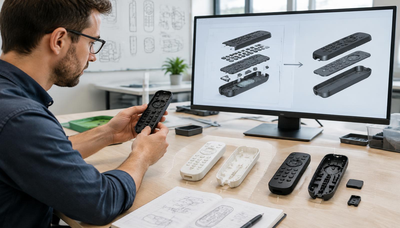
Define Manufacturing Success before Revising the Design
Design for manufacturing, often abbreviated DFM, aligns product requirements with a realistic production method. Its purpose is not simply to remove components or negotiate a cheaper quotation. The goal is repeatable production of acceptable products at a commercially workable cost, with important risks understood before scale increases.
Start by identifying intended use, performance requirements, expected demand, and service life. Separate safety and functional characteristics from cosmetic preferences and assumptions inherited from an early prototype. Assign a technical owner who can decide which supplier recommendations preserve the product’s intended value.
Record launch quantities, reorder expectations, target lead times, and tooling constraints alongside engineering requirements. A process suitable for a small pilot may become inefficient at larger volumes. Equally, an expensive dedicated tool may be difficult to justify when demand remains uncertain.
Select a Process That Fits Geometry and Demand
Manufacturing processes have different strengths that should influence product geometry. Machining can provide flexibility, while molding, casting, stamping, and forming may support efficient repetition with greater upfront commitment. Review the whole route rather than assuming one familiar process is automatically the best choice.
Ask suppliers to describe equipment, fixtures, secondary operations, and subcontracted activities. Identify features that need repeated setups, specialized tools, difficult handling, or unusually skilled intervention. These details reveal where the design creates hidden cost or depends on conditions that may not remain stable.
- Share controlled drawings, functional requirements, volume assumptions, and appearance references.
- Request the proposed process route, tooling needs, fixtures, and important manufacturing risks.
- Compare feasible options using total cost, quality controls, lead time, and change flexibility.
- Document the selected approach and unresolved issues before authorizing dedicated tooling.
Simplify Features without Sacrificing Function
Challenge every feature by asking which necessary function it performs. Decorative steps, inaccessible pockets, unique brackets, and unnecessary fasteners can add work without improving customer value. Remove complexity only after checking that the proposed change does not transfer greater difficulty to finishing, inspection, or assembly.
Apply guidance appropriate to the actual process rather than universal rules detached from context. Molded parts may need suitable draft, wall transitions, and geometry compatible with the selected resin. Machined parts may benefit from accessible features, practical internal radii, and fewer setups, while preserving important interfaces.
Part consolidation requires a balanced evaluation rather than a simple component-count target. Integrating several pieces can increase tool complexity, enlarge scrap losses, or make repair uneconomic. Compare assembly savings against tooling risk, replacement costs, inspection access, and the consequences of failure.
Evaluate Cost across the Complete Production Route
Piece price alone cannot demonstrate that a redesign saves money. Include tooling amortization, material usage, finishing, inspection, rework, packaging, and likely maintenance in the comparison. Keep quantities and quality requirements consistent so quotations do not appear competitive merely because they cover different work.
Distinguish measured savings from estimates and state the assumptions behind each calculation. Assembly trials may exclude handling, breaks, line imbalance, or normal variation between operators. Evaluate sensitivity to demand and yield before presenting an attractive trial result as a dependable annual saving.
Example
Illustrative decision scenario
All figures are illustrative. A control housing originally uses eight screws and takes 120 seconds to assemble. A revised design uses four screws and locating features, taking 85 seconds in a trial. Across 3,000 units, the nominal difference is about 29 assembly hours before handling, rework, or line-balance allowances. The revised tooling costs an additional $2,000, so labor savings alone may not justify the change. Retention, durability, service access, and inspection also require validation before the redesign can be approved.
Set Functional Tolerances and Clear Datums
Tolerances should follow function rather than signal how sophisticated a drawing appears. Tight limits on every dimension may force slower equipment, extra sorting, or unnecessary scrap. Identify the dimensions controlling alignment, sealing, movement, fit, and safety before demanding exceptional precision.
Review how dimensions accumulate across mating components and include coatings, temperature effects, and material variation where relevant. Establish datums that connect manufacturing and inspection to the product’s functional interfaces. Use geometric tolerancing correctly when appropriate and agree how suppliers will measure the specified characteristics.
Request evidence relevant to the proposed equipment, material, and process conditions. A supplier’s best isolated measurement does not establish routine production capability. When representative evidence is unavailable, record the uncertainty and require suitable trials before treating the tolerance as proven.
Make Assembly and Inspection Practical
Assembly should be accessible, understandable, and difficult to perform incorrectly. Look for parts that can be reversed, confused, trapped, or installed in the wrong sequence. Locating features and orientation controls may prevent errors more reliably than instructions asking operators to pay closer attention.
Review tool clearance, cable routing, adhesive application, fastener access, and the ability to check completed joints. Standardizing fasteners can reduce changeovers and purchasing complexity when strength and compatibility remain suitable. Preserve service access where the product is intended to be repaired or maintained.
Design important characteristics so they can be verified economically and reliably. Avoid concealing critical joints before inspection, and define justified functional tests where direct measurement is impractical. Connect drawing requirements to a control plan covering methods, responsibilities, acceptance criteria, and reactions to failures.
Validate the Design with Production-Intent Trials
A successful prototype is not automatic evidence of production readiness. It may use substitute materials, hand finishing, or assembly methods unsuitable for routine manufacturing. Identify those differences before interpreting prototype appearance, strength, or fit as proof that the intended process will perform consistently.
Define trial objectives, sample coverage, acceptance criteria, and required records before work begins. Use intended materials, tooling, equipment, finishes, and assembly methods wherever practical. Record defects and rework as well as successful samples so the review does not conceal the effort needed to achieve acceptable output.
Investigate whether trial failures arise from design, tooling, process settings, materials, or work instructions. Assign corrective actions and repeat affected validation after meaningful changes. A short successful run may still leave questions about aging, tool wear, material batches, or longer-term process stability.
Release checklist
- ✓Critical functions and customer-facing requirements remain protected.
- ✓The manufacturing route and subcontracted operations are understood.
- ✓Geometry is appropriate for intended materials, tooling, and equipment.
- ✓Critical dimensions have clear datums and feasible inspection methods.
- ✓Assembly orientation, access, and error prevention have been reviewed.
- ✓Production-intent trials cover important failure modes and open risks.
- ✓Approved drawings, samples, and instructions carry consistent revisions.
- ✓Unresolved issues have named owners and explicit release conditions.
Control Changes and Review Actual Results
Implement approved changes through coordinated updates to drawings, bills of materials, work instructions, and quality documents. Define the changeover point and disposition of existing stock before introducing revised parts. Otherwise, incompatible versions can reach the same assembly line or become difficult to distinguish during complaint investigations.
Compare actual production results with the original DFM objectives using accepted-unit cost, defects, rework, assembly effort, and delivery performance. Keep product configurations and measurement periods comparable rather than selecting only favorable observations. Use the evidence to refine assumptions and prioritize further improvements.
Source & Brand coordinates OEM/ODM discussions, supplier verification, and quality requirements, but does not own factories or issue inspection certificates. Buyers should retain clear technical approval authority and arrange competent verification where needed. Continued supplier feedback is valuable only when recommendations pass through documented evaluation and release.
Use a joint drawing review to classify dimensions as critical, functional or cosmetic. For an injection-molded housing, snap-fit geometry and screw alignment may need tighter control than an unseen internal surface. Ask how each critical dimension will be measured on the production line and whether the proposed tolerance is realistic for the process. Review gate location, parting lines and assembly access before approving tooling. Record decisions in the drawing rather than leaving them in meeting notes. Design-for-manufacturing work should simplify production without quietly weakening the product’s essential fit, strength or intended function. Validate changes with representative production samples.
Frequently asked questions
When should DFM begin?
Begin while the design can change without major tooling expense. Repeat the review as materials, suppliers, and production methods become definite, and revisit it after significant changes.
Does DFM always mean fewer parts?
No, because separating a component can simplify tooling, reduce scrap exposure, or improve repairability. Evaluate the complete production and service implications rather than treating part count as the main objective.
Should tolerances match a supplier’s best result?
No, tolerances should reflect functional needs and realistic repeatable capability. Designing around exceptional results may create unnecessary expense and too little margin for ordinary variation.
Can a prototype authorize volume production?
A prototype alone often leaves important manufacturing questions unanswered. Use production-intent trials and risk-based validation to determine what the planned process can actually deliver.
Who approves supplier design changes?
The buyer’s designated technical authority should approve changes affecting the controlled product definition. Suppliers and sourcing partners can recommend improvements, but those recommendations should not bypass evaluation and release.
Key takeaway
Design for manufacturing connects essential product requirements with processes capable of delivering them repeatedly. Combine practical geometry, functional tolerances, reliable assembly, and production evidence, then control changes so cost improvements do not undermine consistency.